Contact:Mr Wang
Mobile :13713335011
Wechat:13713335011
Fax:0769-89783666
Tel :0769-89783666
Email:wym@oikwan.com.cn
Add :5th Floor, Building D, No. 19 Zhugang Road, Shatou, Chang'an Town, Dongguan City

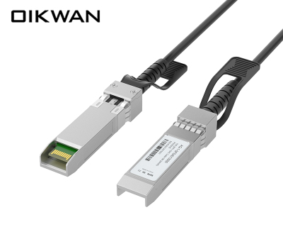
25Gb/s SFP28 Active Optical Cable
Product Features
1.Up to 28Gbps Data rate per channel
2.Maximum link length of 100m links on OM3 multimode fiber
3.High Reliability 850nm VCSEL technology
4.Electrically hot-pluggable
5.Electrical interface compliant to SFF-8431
6.Case operating temperature range: 0°C to 70°C
7.Power dissipation < 1.0W per cable end
Applications
25G Ethernet
Data center and Fiber channel
Standard
Compliant to SFF-8431
Compliant to SFF 8472
RoHS Compliant
Product selection
Part Number | Product description |
SFP28-AOC-XXX | XXX=different cable lengths on OM3 Multimode Fiber (MMF) –Note |
XXX | cable lengths on OM3 Multimode Fiber (MMF) |
003 | 3m |
005 | 5m |
007 | 7m |
010 | 10m |
050 | 50m |
100 | 100m |
Note:
1. Cable length =<100m
2 . More detail product selection and cable lengths,please contact sales
Ⅰ Absolute Maximum Ratings
Parameter | Symbol | Min. | Typ. | Max. | Unit | Note |
Storage Temperature | Ts | -40 | - | 85 | ºC | |
Relative Humidity | RH | 5 | - | 95 | % | |
Power Supply Voltage | VCC | -0.3 | - | 4 | V | |
Signal Input Voltage | Vcc-0.3 | - | Vcc+0.3 | V |
Ⅱ Recommended Operating Conditions
Parameter | Symbol | Min. | Typ. | Max. | Unit | Note |
Case Operating Temperature | Tcase | 0 | - | 70 | ºC | Without air flow |
Power Supply Voltage | VCC | 3.14 | 3.3 | 3.46 | V | |
Power Supply Current | ICC | - | 300 | mA | per cable end | |
Data Rate | BR | 25.78 | Gbps |
Ⅲ General Product Characteristics
Parameter | Value | Unit | Notes |
Module Form Factor | SFP+ | ||
Maximum Data Rate | 28 | Gb/s | |
Standard Cable Lengths | 3, 5, 7, 10, 50, 100 | meters | Other lengths may be available upon request (<= 100m OM3) |
Protocols Supported | Typical applications include Infiniband, Fibre Channel, 25G Ethernet | ||
Electrical Interface and Pin-out | 20-pin edge connector | Pin-out as defined by the SFP+ MSA | |
Standard Optical Cable Type | Multimode ribbon fiber cable assembly | ||
Maximum Power Consumption per End | 1.0 | W | per cable end |
Management Interface | Serial, I2C-based, 400 kHz maximum frequency | As defined by the SFP+ MSA |
Note:Low rate is 24~26Gb/s&High rate is 25~28Gb/s, different rate range has different register setting ,not auto- Negotiatio
IV. Electrical Characteristics
Parameter | Symbol | Min | Typ | Max | Unit | NOTE |
Supply Voltage | VccT,VccR | 3.14 | 3.3 | 3.46 | V | |
Supply Current | Icc | 300 | mA | |||
Transmitter | ||||||
Differential data input swing | Vin,pp | 50 | 900 | mV | 1 | |
Single ended input voltage tolerance
| VinT
| -0.3 | 4.0 | V | ||
Receiver | ||||||
Vout,pp | 300 | 850 | mV | 2 | ||
Single-ended output voltage
| -0.3 | 4.0 | V |
Notes:
1. AC coupled internally. Self-biasing 100Ω differential input.
2. AC coupled with 100Ω differential output impedance.
V. Pin Assignment
![]()
Pin | Symbol | Name/Description | NOTE |
1 | VEET | Transmitter Ground (Common with Receiver Ground) | 1 |
2 | TFAULT | Transmitter Fault. | 2 |
3 | TDIS | Transmitter Disable. Laser output disabled on high or open. | 3 |
4 | SDA | 2-wire Serial Interface Data Line | 4 |
5 | SCL | 2-wire Serial Interface Clock Line | 4 |
6 | MOD_ABS | Module Absent. Grounded within the module | 4 |
7 | RS0 | Rate Select 0 | 5 |
8 | LOS | Loss of Signal indication. Logic 0 indicates normal operation. | 6 |
9 | RS1 | No connection required | 1 |
10 | VEER | Receiver Ground (Common with Transmitter Ground) | 1 |
11 | VEER | Receiver Ground (Common with Transmitter Ground) | 1 |
12 | RD- | Receiver Inverted DATA out. AC Coupled | |
13 | RD+ | Receiver Non-inverted DATA out. AC Coupled | |
14 | VEER | Receiver Ground (Common with Transmitter Ground) | 1 |
15 | VCCR | Receiver Power Supply | |
16 | VCCT | Transmitter Power Supply | |
17 | VEET | Transmitter Ground (Common with Receiver Ground) | 1 |
18 | TD+ | Transmitter Non-Inverted DATA in. AC Coupled. | |
19 | TD- | Transmitter Inverted DATA in. AC Coupled. | |
20 | VEET | Transmitter Ground (Common with Receiver Ground) | 1 |
Notes:
1. Circuit ground is internally isolated from chassis ground.
2. TFAULT is an open collector/drain output, which should be pulled up with a 4.7k – 10k Ohms resistor on the host board if intended for use. Pull up voltage should be between 2.0V to Vcc + 0.3V.A high output indicates a transmitter fault caused by either the TX bias current or the TX output power exceeding the preset alarm thresholds. A low output indicates normal operation. In the low state, the output is pulled to <0.8V.
3. Laser output disabled on TDIS >2.0V or open, enabled on TDIS <0.8V.
4. Should be pulled up with 4.7kΩ- 10kΩ host board to a voltage between 2.0V and 3.6V. MOD_ABS pulls line low to indicate module is plugged in.
5. Internally pulled down per SFF-8431 Rev 4.1.
6. LOS is open collector output. It should be pulled up with 4.7kΩ – 10kΩ on host board to a voltage between 2.0V and 3.6V. Logic 0 indicates normal operation; logic 1 indicates loss of signal.
VI. Host - Transceiver Interface Block Diagram
![]()
VII. Outline Dimensions
![]()
 25G SFP28 AOC-Datasheet.pdf